How to Choose the Right Inductive Proximity Sensor for Your Application

In most industrial scenarios, selecting an inductive proximity sensor is a frustrating challenge for engineers and technical buyers. Choosing the wrong sensor can lead to frequent failures, unstable detection, and compromised long-term operation—issues that disrupt production schedules and increase maintenance costs.
The root cause, as noted earlier, is rarely a product defect but rather a mismatch between the sensor and application requirements. This guide is designed to address this core pain point: it starts with your actual application needs, systematically breaks down key selection dimensions, including operating conditions, critical parameters, installation details, and environmental factors, and provides actionable guidance to help you avoid selection pitfalls.
By following the framework outlined here, you can select an inductive proximity sensor that ensures reliability, stability, and seamless integration with your system throughout its entire service life.
Understanding Your Application Requirements First
When selecting an inductive proximity sensor, the correct approach starts with your application, not the product itself. In most industrial applications, jumping straight to product specifications without clarifying on-site needs is a common root cause of selection errors. The key is to systematically identify and document critical operating condition variables that directly dictate sensor performance and long-term operation.
-
Define the target material—specifically the metal type, as inductive proximity sensors react differently to ferrous and non-ferrous metals under typical operating conditions.
-
Clarify the exact detection distance requirement, which serves as a baseline for subsequent parameter matching.
-
Map out installation constraints early, such as available mounting space and access for maintenance, as these will narrow down viable sensor form factors.
-
Assess the operating environment, including the presence of dust, oil, or vibration, as these factors directly impact reliability and stability.
A critical point to emphasize: Most sensor failures are selection-related, not product defects. Choosing a sensor that cannot accommodate your specific application conditions will lead to frequent malfunctions, even if the product itself meets quality standards. This underscores why aligning sensor capabilities with application requirements is the foundational step in ensuring long-term operation.
Key Parameters That Affect Sensor Selection
In addition to application requirements, understanding core technical parameters is essential for making an informed selection. These parameters act as the bridge between your on-site needs and the sensor’s capabilities, and they are also critical for ensuring compatibility with your existing systems.
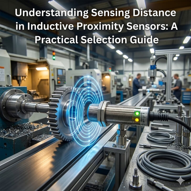
Sensing Distance and Target Size
A common misconception in sensor selection is equating nominal sensing distance with actual detection distance. Under typical operating conditions, the nominal sensing distance provided by manufacturers is tested with a standard-sized metal test plate. If your target size is smaller than this standard test plate, the actual sensing range will be significantly reduced. This can lead to missed detections or unstable performance during long-term operation.
When evaluating sensing distance, you must ask: What is the smallest target size in my application? What happens if the actual sensing distance falls short of the required range? Answering these questions ensures that the selected sensor can reliably detect targets under real-world conditions.
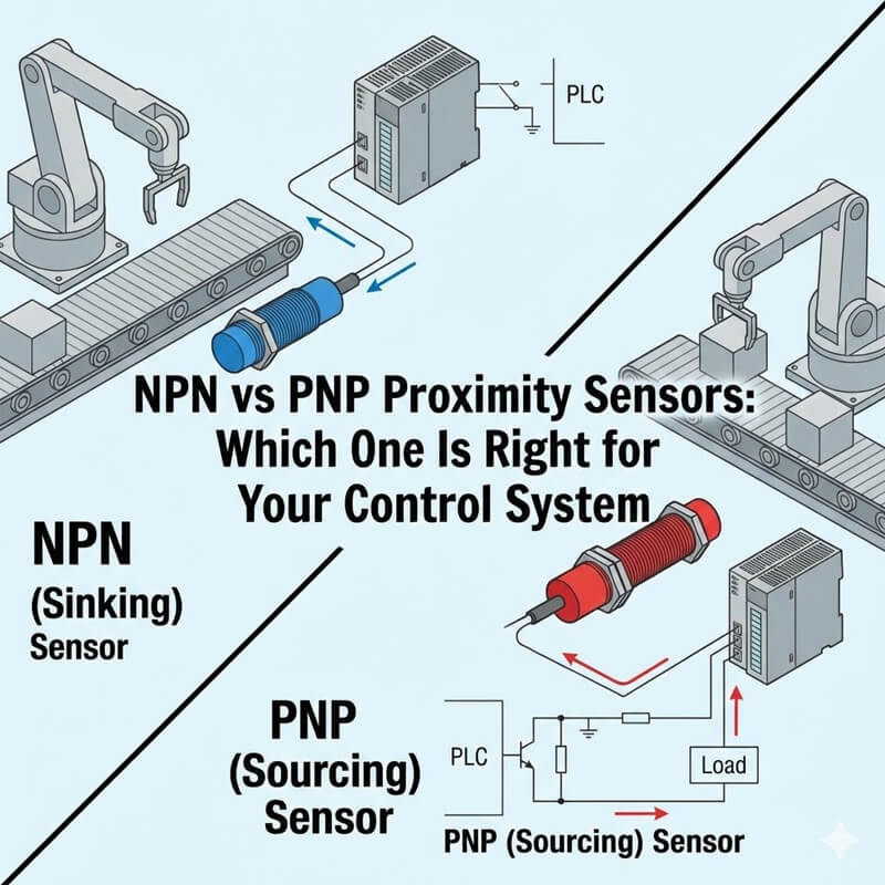
Output Type and Control System Compatibility
The sensor’s output type directly impacts its compatibility with your control system, particularly with PLCs (Programmable Logic Controllers), which are ubiquitous in industrial settings. The choice between NPN, PNP, NO (Normally Open), and NC (Normally Closed) outputs is not a trivial one—it has system-level implications for how the sensor communicates with your control logic.
Under typical operating conditions, NPN outputs are more commonly used in certain regional industrial setups, while PNP outputs are preferred in others. NO outputs are suitable for applications where the sensor should trigger a signal when a target is detected, while NC outputs are used when a loss of detection (e.g., target removal) needs to initiate a response.
* Using an output type incompatible with your PLC will result in communication failures, compromising the entire control system’s stability. It is not recommended for long-term use when the output type does not match the control system’s requirements.
Installation Considerations Often Overlooked
Installation is a critical factor in sensor performance that is often underestimated. Even the most well-selected sensor will fail to deliver reliable results if installed incorrectly, leading to instability and reduced long-term operation capabilities. Two key installation aspects demand special attention.
Flush vs Non-Flush Mounting
The choice between flush and non-flush mounting directly affects both sensor performance and installation flexibility. Flush mounting allows the sensor’s sensing face to be level with the surrounding metal surface, saving space in compact installations. However, metal embedding during flush mounting can interfere with the sensor’s electromagnetic field, potentially reducing sensing distance or causing false triggers. Non-flush mounting, where the sensor protrudes slightly from the mounting surface, avoids this interference but requires more clearance.
This distinction is particularly important as it lays the groundwork for detailed installation guidelines covered in our subsequent article (link to be added: “Flush vs Non-Flush Mounting: Best Practices for Inductive Proximity Sensors”). Proper mounting selection ensures installation stability and prevents unnecessary performance degradation.
Mounting Position and Mechanical Stress
Mounting position and the mechanical stress exerted on the sensor during installation and operation are often overlooked but critical for long-term reliability. Vibrations common in industrial environments can cause sensor loosening or offset over time, leading to detection instability. Similarly, improper mounting torque or misalignment can introduce mechanical stress that damages the sensor’s internal components, even if the sensor is rated for vibration resistance.
*Under typical operating conditions, it is recommended to use mounting hardware that matches the sensor’s specifications and to ensure secure fixation to minimize vibration transfer. When the mounting position is prone to significant vibration or mechanical shock, additional damping measures should be considered to protect the sensor and maintain detection stability.
Environmental Factors That Impact Long-Term Reliability
The operating environment is a decisive factor in the long-term reliability and stability of inductive proximity sensors. Even a sensor perfectly matched to application requirements and installed correctly will fail prematurely if exposed to environmental conditions beyond its tolerance. Two key environmental factors demand thorough evaluation.
Temperature and Ambient Conditions
Temperature extremes—whether high or low—can severely impact sensor performance and lifespan. Under typical operating conditions, inductive proximity sensors have a specified temperature range, and operating outside this range can lead to multiple issues. For example, high temperatures may cause signal drift, reducing detection accuracy, while low temperatures can compromise the flexibility of sealing materials, increasing the risk of moisture ingress. In extreme cases, temperature超限 (exceeding limits) can permanently damage the sensor’s electronic components, rendering it inoperable.
It is not recommended for long-term use when the ambient temperature consistently falls outside the sensor’s rated range. Assessing seasonal temperature fluctuations and heat generation from nearby equipment is essential to ensure the sensor can maintain stability over time.
Ingress Protection and Contamination
Ingress Protection (IP) rating is a key indicator of a sensor’s ability to resist dust, water, and other contaminants, but it is not a universal guarantee. In most industrial applications, sensors may be exposed to a combination of contaminants—such as oil mist, abrasive dust, or corrosive fluids—that can exceed the limits of the IP rating.
For example, an IP67-rated sensor can withstand temporary immersion in water but may fail if continuously exposed to high-pressure oil jets. Contamination can accumulate on the sensing face, blocking the electromagnetic field and causing detection failures. Regular cleaning and selecting a sensor with an IP rating appropriate for the specific contamination type are critical for ensuring long-term operation.
*Remember: the IP rating provides a baseline of protection, not immunity to all environmental hazards.
Final Checklist Before Making a Selection
To ensure you select the right inductive proximity sensor, use the following engineering-focused checklist to verify alignment with your application needs, parameters, installation, and environment:
-
Application Requirements: Have you clearly defined the target material, required detection distance, installation constraints, and environmental conditions?
-
Sensing Distance: Is the sensor’s nominal sensing distance adjusted for the actual target size (accounting for reduced range if the target is smaller than the standard test plate)?
-
Output Compatibility: Does the sensor’s output type (NPN/PNP/NO/NC) match your PLC and control system requirements?
-
Installation Type: Have you selected flush or non-flush mounting based on space constraints and electromagnetic interference considerations?
-
Mechanical Stability: Is the mounting position designed to minimize vibration, offset, and mechanical stress?
-
Temperature Tolerance: Does the sensor’s rated temperature range cover all seasonal and operational temperature fluctuations in your application?
-
Ingress Protection: Is the IP rating sufficient for the specific contaminants (dust, oil, water) present in the operating environment?
-
Long-Term Reliability: Will the sensor maintain stability and performance for the required lifespan under the specified operating conditions?
Final Recommendation: Prioritize sensors that align with the majority of your checklist items, with non-negotiable requirements (e.g., temperature range, output compatibility) as hard constraints. If a sensor falls short on a critical item, it is not suitable for long-term use—even if it meets other criteria. Most importantly, validate your selection with a sample test in the actual application environment whenever possible, as this is the most reliable way to confirm stability and reliability before full-scale deployment.
By following this structured approach—starting with application requirements, evaluating key parameters, addressing installation considerations, accounting for environmental factors, and verifying with the final checklist—you can avoid selection-related failures and ensure the inductive proximity sensor delivers consistent, reliable performance for long-term operation.
Explore Bedook: Your Trusted Sensor Manufacturer
At Bedook, we specialize in designing, developing, and manufacturing a comprehensive range of proximity sensors and switches. Our extensive product lineup includes:
- Inductive Proximity Sensors
- Capacitive Proximity Sensors
- Photoelectric Sensors
- Ultrasonic Sensors
- Solid State Relays
- Various Accessories
With over 10,000 detailed product variations and a robust R&D team, we take pride in our ability to meet your unique requirements with tailored solutions and reliable performance.
Whether you’re seeking off-the-shelf products or customized designs, Bedook offers the expertise and production capacity to ensure your satisfaction.
Get in Touch Today!
We value your interest in our products and warmly encourage you to send us an inquiry. Let us help you find the perfect sensor solution for your application.
Thank you for considering Bedook—your trusted partner in innovation and quality manufacturing. We look forward to collaborating with you!
 Inductive Proximity Sensors in Industrial Automation – Technical Knowledge for Industrial Applications
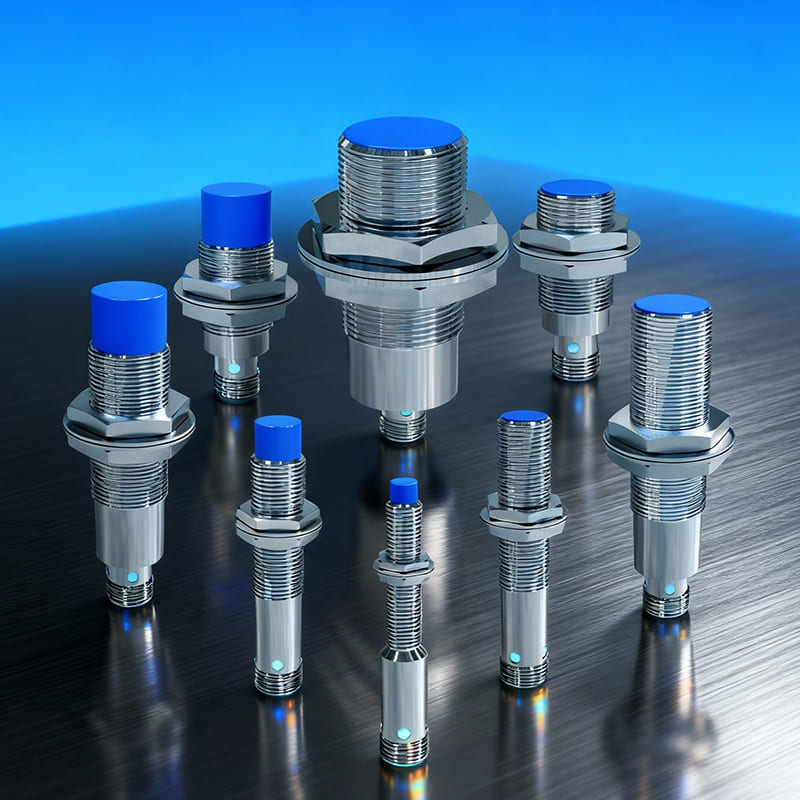 Inductive vs Capacitive Proximity Sensors: Industrial Selection Guide