Understanding Sensing Distance in Inductive Proximity Sensors: A Practical Selection Guide
In real industrial installations, the actual sensing distance of an inductive proximity sensor is often significantly shorter than the nominal value stated in the datasheet. This difference does not indicate a defect in the sensor itself; rather, it results from the combined influence of target characteristics, installation methods, and operating environment.
For engineers and procurement professionals, understanding sensing distance is not about memorizing definitions. The real objective is to anticipate potential failure scenarios, avoid rework caused by improper selection, and ensure the control system’s long-term stability. In essence, sensing distance is a system-level outcome, determined jointly by the sensor, the target, the installation conditions, and the environment—not a fixed, standalone parameter.
Why Nominal Sensing Distance Rarely Matches Real Applications
One of the most common issues during commissioning is the following:
“The datasheet specifies an 8 mm sensing distance, but in the field, the reliable detection distance is only about 4 mm.”
This gap usually originates from a misunderstanding of what nominal sensing distance represents and from overlooking standard test conditions. Clarifying this misconception is the first step toward reliable sensor selection.
Nominal Sensing Distance and Standard Test Conditions
Nominal sensing distance (typically indicated as Sn in datasheets) is a reference value measured under strictly defined standard conditions. It is intended for performance comparison—not as a guarantee for real-world installations. These standard conditions generally include:
-
Target material: Standard low-carbon steel (Fe 37), which provides optimal electromagnetic response due to its favorable magnetic permeability and electrical conductivity.
-
Target size: A square or circular metal plate with surface dimensions at least 1.5 times the diameter of the sensing face (for example, a 27 mm × 27 mm plate for an M18 sensor).
-
Environmental conditions: Ambient temperature of 23 ± 5 °C, no electromagnetic interference, no vibration, and a stable supply voltage within ±10% of the rated value.
These conditions are in place to ensure comparability across different sensor models. They do not represent typical industrial environments. Confusing standard test conditions with real operating conditions is a primary reason why expected and actual sensing performance differ.
Usable vs. Reliable Sensing Distance
To avoid ambiguity, it is important to distinguish between two practical concepts:
-
Usable sensing distance: The maximum distance at which the sensor can trigger a signal. At this limit, operation may be intermittent and sensitive to environmental fluctuations.
-
Reliable sensing distance: The distance at which the sensor can operate consistently over time, without false triggering, missed detections, or degradation in repeatability.
The difference between these two values defines the engineering safety margin. Selecting a sensor based solely on usable distance almost inevitably leads to instability and downtime. Long-term system reliability depends on maintaining a sufficient margin below the nominal limit.
Key Factors That Reduce Sensing Distance in Practice
The nominal sensing distance stated in datasheets is often reduced by real-world conditions. Understanding how these factors affect performance allows engineers to anticipate losses and make rational selection decisions.
Target Material and Size
Inductive proximity sensors operate based on electromagnetic induction. As a result, both target material and target size have a direct impact on induced current strength and, consequently, on sensing distance.
-
Material effects: Non-ferromagnetic metals such as aluminum, copper, and austenitic stainless steel (e.g., 304) typically provide only 30–70% of the sensing distance achieved with Fe 37 steel. Low-conductivity metals such as lead or tin may reduce sensing distance to below 30% of the nominal value.
-
Size effects: In many applications, the target is a small component—such as a screw, pin, or gear tooth—rather than a standard test plate. When the target surface area is reduced, sensing distance decreases proportionally. For example, a target with only 50% of the standard surface area may reduce sensing distance by approximately 40–50%.
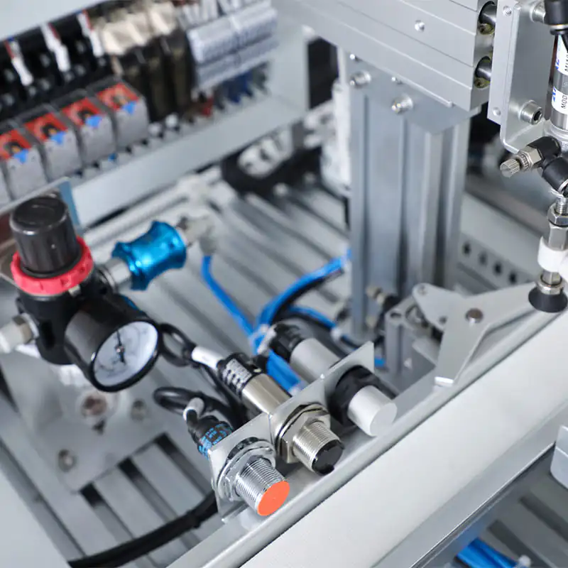
Flush vs. Non-Flush Installation
The installation method is another critical factor and a frequent source of misunderstanding.
-
Non-flush installation: The sensing face is not surrounded by metal. This configuration allows the electromagnetic field to develop freely, resulting in sensing distances closer to the nominal value (subject to other influencing factors).
-
Flush installation: The sensing face is mounted level with surrounding metal surfaces. While often chosen to prevent mechanical damage, the surrounding metal suppresses the electromagnetic field. In practice, flush-mounted sensors typically exhibit sensing distances 15–30% shorter than their non-flush counterparts.
Many engineers assume flush installation is “safer,” without accounting for its impact on sensing distance—often leading to insufficient detection range and missed signals.
Environmental Conditions
Industrial environments are rarely ideal. Temperature, vibration, and electromagnetic interference can all cause sensing distance to deviate from nominal values, especially over long-term operation.
-
Temperature drift: When ambient temperature moves outside the standard test range, electronic component characteristics change. At temperatures above 60 °C, sensing distance may decrease by 10–20%. At temperatures below –10 °C, sensing distance may also shrink, accompanied by slower response times.
-
Vibration and mechanical offset: Continuous vibration in machinery such as conveyors or machine tools can cause small positional shifts between sensor and target. Over time, mechanical wear amplifies these effects, reducing effective sensing distance.
-
Electromagnetic interference: Environments with frequency converters, welding equipment, or high-power motors can disturb the sensor’s electromagnetic field, leading to unstable detection or false triggering. In severe cases, effective sensing distance may be reduced by more than 30%.
Why a Longer Sensing Distance Is Not Always Better
From a system integration perspective, many engineers instinctively prefer sensors with longer nominal sensing distances, assuming this increases installation flexibility. In practice, however, longer distance does not necessarily mean better performance—and may even increase instability risk.
Signal Stability and False Triggering
Inductive sensors operate with a boundary region near the nominal sensing limit, where signal strength is weak and noise immunity is low. Continuous operation within this region significantly increases the likelihood of false triggering or missed detections.
For example, a sensor with a nominal sensing distance of 15 mm may operate stably at 10 mm. At 14 mm—close to the rated limit—minor temperature changes or vibration can cause intermittent switching. In automated systems, such instability is a common root cause of production interruptions.
Repeatability and Detection Consistency
Industrial control systems prioritize repeatability and consistency over maximum reach. Repeatability refers to how consistently a sensor triggers at the same distance under identical conditions.
Sensors operating near their maximum rated distance often exhibit poorer repeatability. Small environmental variations can cause noticeable shifts in trigger point. Operating well within the rated range, by contrast, improves consistency and ensures uniform detection across all cycles.
How to Select Sensing Distance with Proper Engineering Margin
The primary objective of sensing distance selection is to avoid rework and system failures. Based on extensive field experience, the most reliable approach is to reserve sufficient engineering margin and select sensors according to actual operating conditions rather than nominal specifications.
Practical Rule of Thumb
A commonly applied and reliable guideline is to set the actual installation distance to approximately 60–70% of the nominal sensing distance. This range accounts for material effects, installation constraints, and environmental influences, keeping the sensor within a stable operating zone.
For example, for a sensor with a nominal sensing distance of 10 mm, the recommended installation distance would be 6–7 mm. If the target is aluminum (with a typical reduction factor of around 0.6), the distance should be further reduced to approximately 4–5 mm to ensure reliable operation.
When to Choose a Sensor with a Higher Nominal Rating
In some applications, even operating at 60–70% of the nominal value may not meet installation requirements—such as when space is limited or target dimensions vary significantly. In these cases, selecting a sensor with a higher nominal sensing distance is safer than forcing a lower-rated sensor to operate at its limit.
For instance, if the required installation distance is 8 mm and the target material is aluminum (reduction factor ≈ 0.6), a sensor with a nominal sensing distance of 15 mm should be selected (8 mm ÷ 0.6 ≈ 13.3 mm). Using a 10 mm sensor would leave insufficient margin and increase the risk of unstable detection. While higher-rated sensors may have slightly higher upfront cost, they significantly reduce the risk of downtime, rework, and false alarms.
Final Recommendation: Prioritize Stability Over Nominal Limits
Ultimately, understanding sensing distance in inductive proximity sensors means recognizing how it degrades under real-world conditions. Sensing distance is not a single fixed value, but a system-dependent result influenced by target material, installation method, and environment.
From an engineering reliability perspective, the correct selection strategy is to avoid over-reliance on nominal datasheet values and not to pursue maximum sensing distance blindly. Instead, prioritize sufficient engineering margin and stable long-term operation.
Based on Bedook’s field experience across thousands of industrial applications, the optimal approach is never “the longest sensing distance possible,” but rather ensuring that the effective sensing distance reliably meets system requirements. By understanding distance reduction, reserving margin, and prioritizing stability, engineers and buyers can avoid common selection pitfalls and significantly improve automation system reliability.
Explore Bedook: Your Trusted Sensor Manufacturer
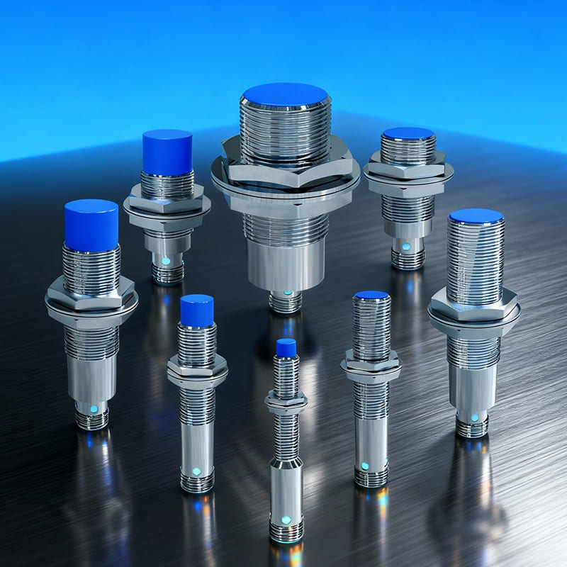
At Bedook, we specialize in designing, developing, and manufacturing a comprehensive range of proximity sensors and switches. Our extensive product lineup includes:
- Inductive Proximity Sensors
- Capacitive Proximity Sensors
- Photoelectric Sensors
- Ultrasonic Sensors
- Solid State Relays
- Various Accessories
With over 10,000 detailed product variations and a robust R&D team, we take pride in our ability to meet your unique requirements with tailored solutions and reliable performance.
Whether you’re seeking off-the-shelf products or customized designs, Bedook offers the expertise and production capacity to ensure your satisfaction.
Get in Touch Today!
We value your interest in our products and warmly encourage you to send us an inquiry. Let us help you find the perfect sensor solution for your application.
Thank you for considering Bedook—your trusted partner in innovation and quality manufacturing. We look forward to collaborating with you!