Inductive proximity sensors are fundamental components in industrial automation, enabling non-contact detection of metallic objects for positioning, presence verification, and process control. Widely deployed across mechanical manufacturing, production lines, material handling, and equipment automation, these sensors deliver fast response times, robust performance, and long service life—when selected and applied correctly.
However, improper selection is a leading cause of automation system failures, including false triggers, missed detections, equipment damage, and unplanned downtime. Common engineering challenges stemming from poor selection include inconsistent detection across different metals, reduced sensor lifespan in harsh environments, signal incompatibility with control systems, and interference from surrounding components.
Engineers, maintenance technicians, system integrators, and procurement specialists involved in industrial automation stand to benefit from mastering the technical nuances of inductive proximity sensor selection. This article outlines the core principles of these sensors, highlights five common selection pitfalls, provides actionable solutions, and shares expert recommendations—equipping industrial professionals to optimize sensor performance and enhance system reliability.
Inductive proximity sensors operate on the principle of electromagnetic induction. A built-in oscillator generates a high-frequency magnetic field around the sensor’s sensing face. When a metallic object enters this magnetic field, eddy currents are induced in the object, causing a change in the oscillator’s amplitude or frequency. The sensor’s signal processing module detects this change and converts it into a digital output signal (on/off) to trigger control actions.
Notably, these sensors exclusively detect metallic objects—non-metallic materials (e.g., plastic, wood, glass) do not interact with the magnetic field and thus cannot be detected. The detection capability varies significantly based on the target material’s electrical conductivity and magnetic permeability.
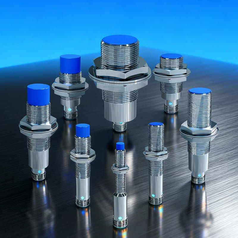
Industrial-grade inductive proximity sensors (such as BEDOOK’s product lines) consist of four core components:
- Oscillator Circuit: Generates the high-frequency magnetic field (typically 100kHz–1MHz) via an inductive coil.
- Sensing Face: The front-end area that emits and receives the magnetic field, usually made of durable materials (plastic, stainless steel, or ceramic) for environmental protection.
- Signal Processing Module: Filters noise, amplifies the induced signal change, and compares it to preset thresholds to generate a stable output.
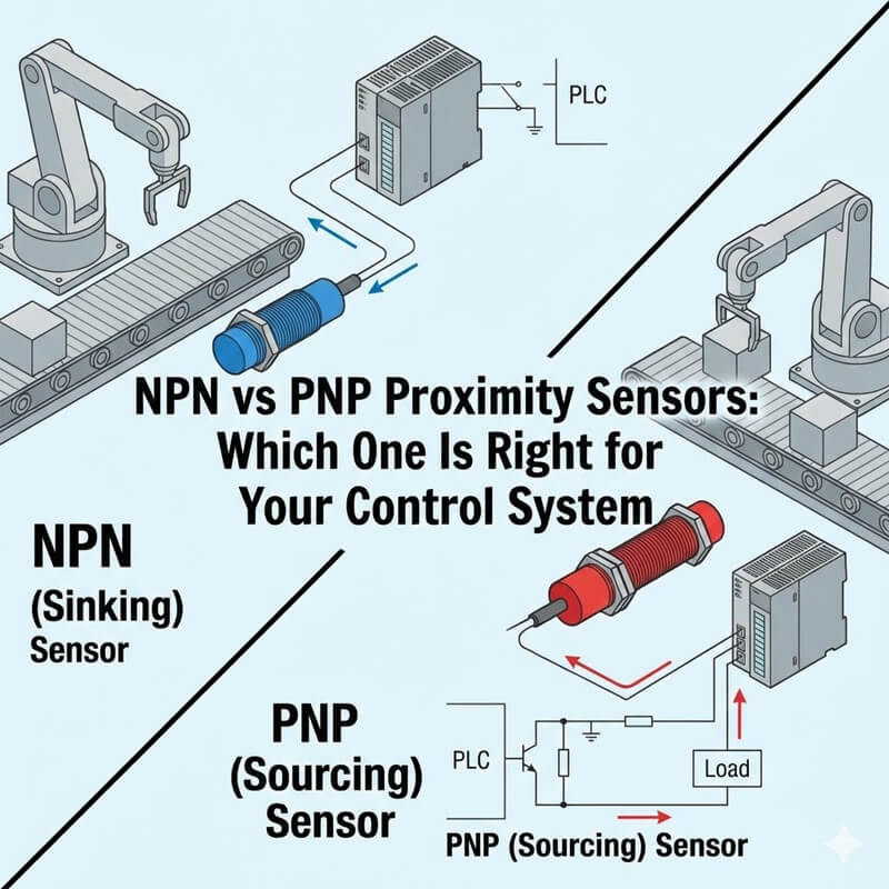
- Output Interface: Delivers signals to control systems (PLCs, controllers) in NPN, PNP, push-pull, or analog (0–10V/4–20mA) formats.
- Rated Detection Distance (Sn): The maximum distance at which the sensor can reliably detect a standard target (typically a 1mm-thick low-carbon steel plate with dimensions matching the sensing face diameter), specified by the manufacturer.
- Material Factor (k): A coefficient representing the sensor’s detection capability for non-ferrous metals relative to steel (e.g., copper k=0.3, aluminum k=0.4, stainless steel k=0.8).
- Response Time: The time taken for the sensor to switch output state after detecting a target, typically <1ms for high-speed applications.
- Protection Rating (IP): Indicates resistance to dust, moisture, and liquids (e.g., IP67, IP68, IP69K).
- Operating Temperature Range: Standard models typically operate between -20°C and 80°C, with high-temperature variants rated up to 150°C.
Industrial environments pose multiple challenges to sensor performance:
- Temperature Fluctuations: Extreme heat or cold can affect detection distance and damage electronic components.
- Contaminants, such as dust, oil, coolants, and corrosive gases, can erode unprotected sensors.
- Electromagnetic Interference (EMI): Nearby motors, inverters, or high-voltage equipment can disrupt sensor signals.
- Installation Constraints: Embedding the sensor in metal panels (flush mounting) or placing it near other metallic components can alter the magnetic field.
Inductive proximity sensors are indispensable across key industrial automation scenarios, where precise, contact-free detection is critical:
- Mechanical Manufacturing: Positioning of machine tools, verification of part clamping, and detection of component presence in assembly lines.
- Material Handling: Conveyor belt speed monitoring, pallet detection, and automated guided vehicle (AGV) navigation.
- Automotive Production: Welding fixture positioning, component feeding verification, and robotic arm end-effector positioning.
- Packaging Machinery: Detection of packaging materials, film roll positioning, and seal integrity verification.
- Energy and Utilities: Valve position monitoring, pump impeller rotation detection, and equipment status sensing.
Different applications demand tailored sensor characteristics:
- High-Speed Production Lines: Require sensors with response times <1ms to keep up with rapid part movement.
- Washdown Environments (e.g., Food Processing): Need IP68/IP69K protection and stainless steel housings to withstand cleaning agents.
- Chemical plants require corrosion-resistant coatings and sealed enclosures to resist acidic and basic gases.
- Precision Positioning: Benefit from analog output sensors (0–10V/4–20mA) for continuous distance measurement.
Correct sensor selection directly translates to operational benefits: reduced downtime (by minimizing false triggers and failures), improved product quality (by ensuring precise process control), and lower maintenance costs (by extending sensor lifespan). For example, selecting a high-temperature ceramic-encapsulated sensor for a welding line prevents premature failure, while choosing a PNP-output sensor for a Siemens PLC avoids signal incompatibility.
This issue arises from differences in electrical conductivity and magnetic permeability across metals—core properties that influence eddy current generation. Ferrous metals (e.g., steel, iron) have high magnetic permeability, resulting in the longest detection distance (100% of the rated Sn). Non-ferrous metals (e.g., copper, aluminum) have lower conductivity, so their actual detection distance may be only 30–80% of the rated Sn.
Solution: Use the material factor (k) to calculate the actual usable distance: Actual Distance = Rated Sn × Material Factor × Safety Margin. For non-ferrous metals, select high-frequency oscillation or universal-type sensors (e.g., BEDOOK’s general-purpose series) that provide more consistent detection across multiple metals. For small or low-conductivity targets, choose sensors with a rated detection distance ≥5mm to compensate for reduced performance.
| Target Metal Type |
Material Factor (k) |
Rated Detection Distance (Sn, Example) |
Actual Installation Distance (with Safety Margin=0.8, Environmental Factor=0.9) |
| Mild Steel (Ferrous) |
1 |
5mm |
5mm × 1.0 × 0.8 × 0.9 = 3.6mm |
| Stainless Steel |
0.8 |
5mm |
5mm × 0.8 × 0.8 × 0.9 = 2.88mm |
| Aluminum (Non-ferrous) |
0.4 |
5mm |
5mm × 0.4 × 0.8 × 0.9 = 1.44mm |
| Copper (Non-ferrous) |
0.3 |
5mm |
5mm × 0.3 × 0.8 × 0.9 = 1.08mm |
| Lead (Low Conductivity) |
0.2 |
5mm |
5mm × 0.2 × 0.8 × 0.9 = 0.72mm |
Note: Calculation formula follows the article’s guidance: Actual Distance = Rated Sn × Material Factor × Safety Margin × Environmental Factor. Values are for reference; confirm with BEDOOK technical specifications for specific models.
Missed detections often occur when relying solely on the nominal rated distance (Sn) without accounting for real-world conditions. The nominal distance is tested under ideal circumstances (standard steel target, room temperature, optimal installation), which rarely match industrial environments.
Solution: Calculate the actual installation distance using the formula: Actual Distance = Rated Sn × Material Factor × Safety Margin × Environmental Factor. Recommended safety margins: 0.7–0.8 (to account for target size variations); environmental factors: 0.8–0.9 for extreme temperatures. Ensure the target’s minimum surface area is ≥1.5 times the sensor’s sensing face diameter. For long-distance detection needs, opt for “triple-distance” series sensors (e.g., BEDOOK’s extended-range models) that offer 3x the detection distance of standard sensors.
Premature failure is primarily caused by mismatched protection ratings and environmental challenges. Over 60% of sensor failures stem from inadequate protection against dust, moisture, chemicals, or temperature extremes.
Solution: Select sensors based on environmental conditions (refer to the table below) and conduct pre-deployment simulation tests (e.g., high-pressure spray for washdown environments).
Incompatibility issues arise from incorrect output type selection (NPN vs. PNP) or mismatched load capacity. NPN and PNP sensors use opposite logic (low-level vs. high-level effective), and selecting the wrong type can cause signal loss or damage to the PLC input module.
Solution: Match the sensor output type to the PLC brand and system requirements (refer to the table below). Verify that the sensor’s maximum load current exceeds the actual load and that the power supply voltage matches the sensor’s rated voltage (typically 12–24V DC).
False triggers are often due to improper mounting (flush vs. non-flush) or electromagnetic interference from surrounding metallic components or equipment.
Solution:
- Select the correct mounting type: Flush mounting (sensor embedded in metal) requires dedicated flush-type sensors (e.g., BEDOOK BB-M18-F series); non-flush mounting allows longer detection distances. For semi-flush mounting, leave 2–5mm of metal-free space around the sensor.
- Reduce EMI: Use shielded cables (RVVP type) with single-end grounding; select EMC-enhanced sensors for high-interference areas.
- Maintain sensor spacing: Keep adjacent sensors at least 3x the rated detection distance apart to avoid mutual magnetic field interference.
- Ensure reliable grounding: Connect the sensor’s metal housing to a dedicated ground terminal to reduce signal noise.
- Prioritize Material Compatibility: Confirm the target is metallic and identify its type (ferrous vs. non-ferrous). Use material factors to calculate actual detection distance and select specialized series (e.g., universal-type for mixed metals) accordingly.
- Calculate Detection Distance Rigorously: Avoid relying solely on nominal Sn. Factor in material, safety, and environmental coefficients to ensure consistent performance in real-world conditions.
- Match to Environmental Challenges: Do not assume “IP67 is sufficient”—select IP68/IP69K for wet environments, high-temperature models for extreme heat, and corrosion-resistant variants for chemical exposure.
- Align with Control System Requirements: Verify output type (NPN/PNP/analog), load capacity, and voltage compatibility with PLCs or controllers to prevent signal loss or equipment damage.
- Follow Mounting Specifications: Use flush-type sensors for embedded installations and non-flush types for maximum detection distance. Maintain required metal-free clearances for semi-flush mounting.
- Minimize Interference: Route shielded cables away from high-voltage lines and motor cables. Ground cables at a single point (preferably the control cabinet) to reduce EMI.
- Optimize Target Alignment: Ensure the target is perpendicular to the sensor’s sensing face and that its surface area meets or exceeds the minimum requirement (1.5x sensing face diameter).
- Secure Cable Connections: Use strain reliefs to prevent cable damage from vibration or pulling, which can cause signal interruptions.
| Mounting Type |
Definition |
Detection Distance Impact |
Key Requirements |
BEDOOK Recommended Series |
| Flush (Embedded) |
Sensor face flush with metal panel |
20–50% shorter than non-flush |
Use dedicated flush-type sensors; no metal obstruction around sensing face |
BB-M18-F Series |
| Non-Flush |
Sensor face protrudes beyond metal panel |
Full rated detection distance (Sn) |
Maintain ≥2× Sn clearance from surrounding metal |
Standard BB-M18 Series |
| Semi-Flush |
Partial embedding in metal (hybrid) |
10–30% shorter than non-flush |
2–5mm metal-free zone around sensor body |
BB-M18 Series (with clearance) |
Application Tip: Flush mounting is ideal for space-constrained environments (e.g., machine tool fixtures); non-flush is preferred for long-distance detection (e.g., conveyor systems).
- Conduct Pre-Installation Testing: Verify sensor performance with the actual target material and under simulated environmental conditions (e.g., temperature cycling, spray testing) before full deployment.
- Adjust Sensitivity (If Applicable): For adjustable models, fine-tune sensitivity to avoid false triggers from distant metallic objects or background interference.
- Document Parameters: Record calibration settings, installation distances, and environmental factors for future reference and troubleshooting.
- Implement Routine Cleaning: Regularly remove dust, oil, or debris from the sensing face (use non-abrasive cleaners) to prevent detection degradation.
- Inspect Cables and Connections: Quarterly check for cable damage, loose terminals, or corrosion. Replace worn cables promptly to avoid moisture ingress.
- Monitor Performance Trends: Track false trigger rates and detection consistency. Replace sensors if performance degrades (e.g., increased response time, frequent failures) to prevent unplanned downtime.
- Adhere to Certification Standards: Ensure sensors comply with ISO9001, CE, and ROHS certifications (as BEDOOK sensors do) to maintain regulatory compliance and quality assurance.
| Selection Dimension |
Critical Check Items |
Common Pitfall to Avoid |
| Target Material |
– Confirm metal type (ferrous/non-ferrous) |
Assuming all metals have the same detection performance |
| – Verify material conductivity/magnetic permeability |
| Detection Distance |
– Calculate actual distance using 4-factor formula |
Relying solely on nominal rated distance (Sn) |
| – Ensure target area ≥1.5× sensing face diameter |
| Environmental Adaptation |
– Match IP rating to environment (dust/water/corrosion) |
Overlooking IP68/IP69K for washdown/chemical environments |
| – Check operating temperature range |
| Output & System Compatibility |
– Align NPN/PNP with PLC brand (Japanese/European/American) |
Mismatched output type causing signal loss or module damage |
| – Verify load current/voltage match |
| Installation & Interference |
– Select correct flush/non-flush type |
Ignoring electromagnetic interference (EMI) from nearby equipment |
| – Use shielded cables + single-end grounding |
| – Maintain ≥3× Sn spacing between sensors |
Usage: Use this checklist to validate selection before deployment; reference BEDOOK’s ISO9001/CE/ROHS-certified product specifications for model-specific details.
- Material compatibility is foundational to reliable detection: Inductive proximity sensors only detect metals, and their performance varies by material—always factor in conductivity, magnetic permeability, and material coefficients when selecting a model.
- Proper distance calculation and environmental matching extend sensor lifespan: Avoid over-reliance on nominal detection distances; instead, apply safety and environmental coefficients, and select protection ratings tailored to on-site conditions.
- Installation and system compatibility prevent costly failures: Match output types to PLCs, minimize electromagnetic interference, and follow mounting guidelines to reduce false triggers and ensure seamless integration.
Aligned with common engineering standards (ISO, IEC), the technical insights and best practices outlined in this article empower industrial professionals to overcome selection challenges and leverage inductive proximity sensors for optimal automation performance. By following BEDOOK’s selection golden rules—material first, distance with margin, environment adaptation, output matching, and correct installation—organizations can achieve more reliable, efficient, and cost-effective industrial operations. For customized selection support, consult BEDOOK’s technical team for application-specific solutions.
Explore Bedook: Your Trusted Sensor Manufacturer
At Bedook, we specialize in designing, developing, and manufacturing a comprehensive range of proximity sensors and switches. Our extensive product lineup includes:
With over 10,000 detailed product variations and a robust R&D team, we take pride in our ability to meet your unique requirements with tailored solutions and reliable performance.
Whether you’re seeking off-the-shelf products or customized designs, Bedook offers the expertise and production capacity to ensure your satisfaction.
We value your interest in our products and warmly encourage you to send us an inquiry. Let us help you find the perfect sensor solution for your application.
Thank you for considering Bedook—your trusted partner in innovation and quality manufacturing. We look forward to collaborating with you!

 Application of BEDOOK Sensor in Foreign Object Detection Machine Industry – Technical Knowledge for Industrial Applications
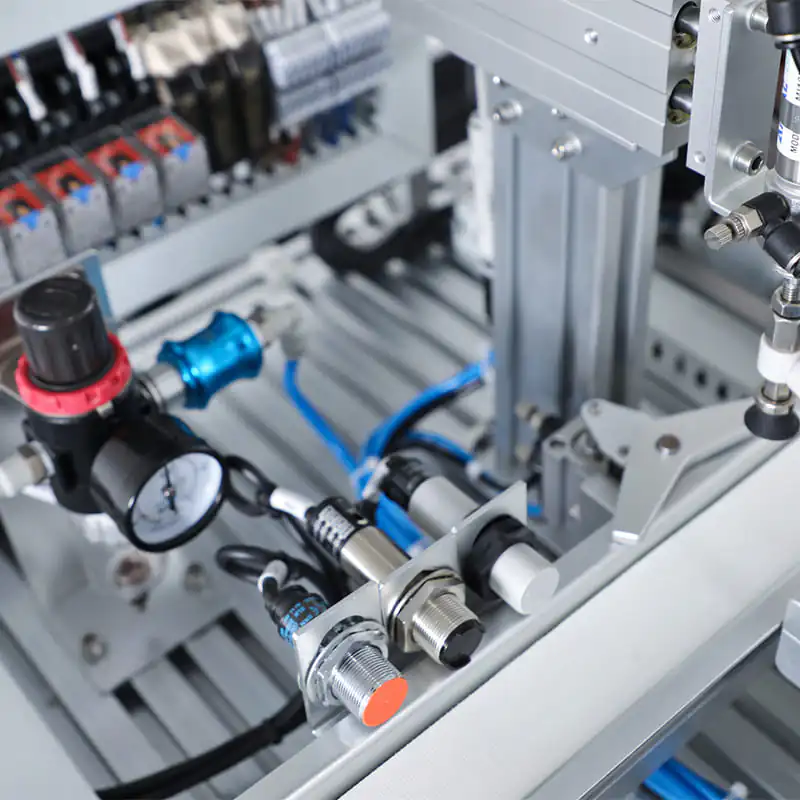 How to Choose the Right Inductive Proximity Sensor for Your Application