Capacitive Proximity Sensor Selection Guide: Dielectric Constants, Liquid Level, and Non-Metallic Target Detection
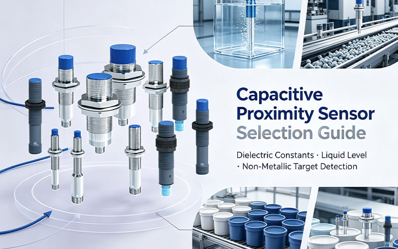
In automated process control, packaging, plastics compounding, and chemical processing, detecting non-metallic objects presents a distinct engineering challenge. While standard inductive proximity sensors are limited to ferrous and non-ferrous metals, capacitive proximity sensors can detect solids, bulk powders, granulates, and liquids.
Whether tracking resin pellets in an injection molding hopper, detecting cardboard packaging flaps, or monitoring liquid levels through thick-walled plastic and sight-glass tubing without fluid contact, capacitive sensors offer a non-invasive, solid-state solution. However, improper selection often leads to field failure: choosing a flush model for sight-glass monitoring, miscalculating material dielectric attenuation, or triggering false alarms from ambient condensation.
This technical guide examines the electrostatic operational physics of capacitive sensing, provides a material dielectric constant reduction matrix, outlines step-by-step sight-glass calibration, and breaks down the Bedook Capacitive Product Matrix to streamline OEM design and procurement.
1. Electrostatic Sensing Physics: The Open-Capacitor Circuit
Unlike inductive sensors that generate an alternating magnetic field via an internal ferrite core coil, a capacitive proximity sensor incorporates an active electrode and a ground shield electrode configured as an open, stray-field capacitor.
The sensor’s internal oscillator circuit is coupled to the active sensing face. In the absence of a target material, the sensor capacitance between the electrodes remains minimal, keeping oscillator feedback below the threshold of oscillation.
- Target Ingress: As any target material (metallic or dielectric non-metal) enters the electrostatic fringe field, the dielectric properties of the medium between the electrodes increase.
- Capacitance Rise: Total capacitance rises according to the formula: C = (εr × ε0 × A) / d.
- Oscillator Activation: Once capacitance crosses the internal comparator threshold, the RC oscillator starts oscillating. The signal processing stage rectifies this oscillation into a discrete DC/AC switching output.
2. Dielectric Constants (εr) and Sensing Range Correction
The rated operating distance (Sn) specified on sensor datasheets is measured using a standardized grounded mild steel plate ($1\text{mm}$ thickness, FE 360). When detecting non-metallic targets, the effective sensing distance (Sr) decreases proportionally based on the target material’s Relative Dielectric Constant (εr).
Effective Distance: Sr = Sn × Km
Materials with a high dielectric constant (such as water or conductive metals) retain higher charge capacitance and can be detected near 100% of the nominal range. Conversely, low-dielectric insulators (such as hydrocarbon oils, dry paper, or polymer pellets) require larger sensor diameters (e.g., M30 over M12) to compensate for range attenuation.
Industrial Target Dielectric Constant & Reduction Factor Matrix
| Target Material Category | Relative Dielectric Constant (εr) | Reduction Factor (Km) | Target Sensing Distance (Based on Sn = 15mm) | Typical Industrial Application |
|---|---|---|---|---|
| Ground Metal (Steel/Alum) | ∞ (Infinite) | 1.00 | 15.0 mm (100%) | Conveyor end-stop indexing, tooling checks |
| Water / Aqueous Solutions | 80.0 | 1.00 | 15.0 mm (100%) | Sight-glass liquid level, overflow alerts |
| Ethanol / Alcohol | 25.0 | 0.85 | 12.7 mm (85%) | Pharmaceutical solvent dosing, distillery lines |
| Glass (Borosilicate / Window) | 5.0 – 10.0 | 0.60 | 9.0 mm (60%) | Glass bottle counting, pane alignment |
| PVC / Polyethylene / POM | 2.5 – 3.5 | 0.35 – 0.40 | 5.2 – 6.0 mm (35-40%) | Plastic container caps, sheet feed control |
| Wood / Paper Board (Moist) | 2.0 – 6.0 | 0.30 – 0.50 | 4.5 – 7.5 mm (30-50%) | Carton packaging presence, lumber sorting |
| Bulk Grains / Cereals | 3.0 – 5.0 | 0.30 | 4.5 mm (30%) | Grain silo high/low level limit switches |
| Hydrocarbon Engine Oil / Fuel | 2.2 | 0.20 | 3.0 mm (20%) | Lubrication reservoir level monitoring |
3. Mechanical Architecture: Flush (Shielded) vs. Non-Flush (Unshielded)
Choosing between flush and non-flush mounting is the most critical mechanical decision when specifying a capacitive sensor. An incorrect choice will either result in premature false-triggering from mounting brackets or an inability to penetrate container walls.
| Design Metric | Flush (Shielded / Quasi-Flush) – Code “B” | Non-Flush (Unshielded) – Code “N” |
|---|---|---|
| Mechanical Housing | Metallic thread extends flush to the sensing face. | Plastic sensing face extends prominently beyond the metal thread. |
| Field Shape | Narrow, axial, directional field directly in front of the face. | Wide, spherical, lateral fringe field expanding 360 degrees. |
| Metallic Flush Mounting | Yes. Can be threaded flush into metal machine blocks. | No. Requires free clearance zone ($≥ 3 \times S_n$) around the head. |
| Through-Wall Level Sensing | Poor. Lateral field is suppressed; cannot compensate for wall thickness. | Ideal. Large fringe field penetrates container wall to detect inner medium. |
| Primary Applications | Dry solid position sensing, zero-clearance machinery, foil detection. | Sight-glass tube liquid levels, silo powder levels, granulate hoppers. |
Golden Engineering Rule: Never specify a Flush (“B”) capacitive sensor for non-contact liquid level monitoring through sight-glasses or plastic tanks. Always select a Non-Flush (“N”) model (e.g., Bedook CN-M18 or CN-M30) to ensure sufficient electrostatic fringe penetration beyond the container wall.
4. Step-by-Step SOP: Calibrating Through-Wall Liquid Level Detection
A frequent challenge for maintenance engineers is tuning a capacitive sensor so it ignores a glass or plastic pipe wall (εr = 3 to 6) while cleanly triggering when water (εr = 80) or liquid chemical rises behind it. Follow this standard operating procedure using the sensor’s multi-turn potentiometer trimmer:
- Mechanical Standoff: Clamp a Non-Flush sensor (e.g., Bedook
CN-M1808P-C11P2) flush against the outside wall of the non-metallic tube (PVC, PTFE, or Borosilicate glass; wall thickness ≤ 4mm). - Drain the Vessel (Empty Condition): Ensure the tube or pipe is completely dry or empty at the sensing level.
- Trim Out the Wall (Initial Calibration):
- If the output LED is ON (sensor detecting the pipe wall), slowly turn the sensitivity potentiometer counter-clockwise until the LED turns completely OFF.
- Continue turning counter-clockwise for an additional ½ to 1 full turn to establish a safety margin against environmental dust and tube wall variations.
- Fill the Vessel (Liquid Present Condition): Allow liquid to rise past the sensor face. The LED must switch solidly ON (verifying water/liquid presence).
- Fine-Tune Boundary Threshold: Note the rotational position where the LED activates with liquid (Point A) and where it stays off with an empty tube (Point B). Position the potentiometer wiper directly in the middle of Point A and Point B. This ensures thermal stability and prevents false switching caused by liquid splashes or thin film residue on the inner wall.
5. Bedook Capacitive Product Matrix & Part Number Decoder
Bedook manufactures a complete spectrum of industrial capacitive proximity sensors ranging from miniature Phi 6.5 mm barrels up to heavy-duty Phi 34 mm and Q-block enclosures. Use the standardized engineering nomenclature below to decode or configure your target part number:
Bedook Model Ordering Code Architecture
| Block | Code | Parameter Group | Available Options & Engineering Meaning |
|---|---|---|---|
| 1 | C / CH | Sensor Type | C: Standard Capacitive | CH: High Temperature Series (≤ 120°C) |
| 2 | B / N | Mounting Type | B: Flush / Quasi-Flush | N: Non-Flush (Unshielded) |
| 3 | M / H / Q | Appearance Profile | M: Threaded Cylindrical | H: Smooth Cylindrical | Q: Rectangular Block |
| 4 | 12 / 18 / 30… | Housing Size | H6.5, M8, M12, M18, M30, Φ34, Q20, Q25, Q30, Q33, Q34 |
| 5 | 02 / 08 / 20… | Sensing Distance | 01: 1mm | 02: 2mm | 08: 8mm | 15: 15mm | 20: 20mm | 25: 25mm |
| 6 | P / N / A / U | Electrical Output | P: PNP 3/4-Wire | N: NPN 3/4-Wire | A: AC 2-Wire | U: AC/DC 2-Wire |
| 7 | C / P | Housing Material | C: Brass, Nickel-Plated / Stainless Steel | P: Engineering Plastics (PBT/PTFE) |
| 8 | 1 / 2 / 3 | Output Mode | 1: Normally Open (N.O.) | 2: Normally Closed (N.C.) | 3: Antivalent (N.O.+N.C.) |
| 9 | 1 / 4 / 5 | Operating Voltage | 1: DC 10–30V | 4: AC 20–250V | 5: AC/DC 20–250V Universal |
| 10 | P / U / F / S / Z | Connection Type | P: PVC | U: PUR | F: PTFE Teflon Cable | S12: M12 Plug | Z12: Pig-tail M12 |
| 11 | 2 / 3 / 5 | Cable Length | 2: 2 Meters | 3: 3 Meters | 5: 5 Meters standard |
6. Electrical Wiring & Connection Reference Table
Bedook capacitive sensors comply strictly with international standard IEC 60947-5-2 wire color codes. Reference the connection matrix below when terminating into PLC digital input cards or motor contactors:
| Interface Category | Wire Color / Pinout | Electrical Function | PLC & Circuit Termination Best Practice |
|---|---|---|---|
| DC 3-Wire (PNP / NPN) 10–30V DC |
Brown (Pin 1) | Supply Positive (+V) | Connect to +24V DC regulated power distribution rail. |
| Blue (Pin 3) | Supply Ground (0V / -V) | Connect to 0V DC Common power rail. | |
| Black (Pin 4) | Switching Output (NO or NC) | PNP: Switches to +24V (Sinking PLC). NPN: Switches to 0V (Sinking PLC). | |
| DC 4-Wire (Antivalent) Complementary NO+NC |
Black (Pin 4) | Normally Open (N.O.) | Primary process signal: ON when target is present. |
| White (Pin 2) | Normally Closed (N.C.) | Diagnostic / wire-break detection line into safety PLC channel. | |
| AC / DC 2-Wire 20–250V AC/DC |
Brown / Line 1 | AC Line (L) or DC (+) | In-Series Connection: Connect the sensor in series with the load (relay coil or PLC input). Minimum holding current > 5mA must be satisfied. |
| Blue / Line 2 | AC Neutral (N) or Load Return |
7. Frequently Asked Questions (FAQ)
Can a capacitive proximity sensor detect objects through a stainless steel pipe?
No. Metals have infinite conductivity and absolute shielding properties. The sensor’s electrostatic field cannot penetrate conductive metal pipes (steel, brass, aluminum). Non-contact internal liquid detection requires non-metallic walls such as PVC, polypropylene, PVDF, Teflon, or borosilicate glass.
How do I prevent false triggering caused by internal tank condensation or dust buildup?
Dust coatings or moisture condensate film on the sensor face can mimic a target. To mitigate this: (1) Use a Non-Flush model positioned with a slight downward angle (10° ~ 15°) to allow droplets to run off; (2) Back off the sensitivity potentiometer by 1 full turn beyond the triggering threshold; (3) For aggressive sticky slurries or chemical tanks, specify Bedook’s specialized PTFE/Plastic shell variants with compensator electrodes.
What is the maximum operating temperature for capacitive proximity switches?
Standard industrial sensors operate between -25℃ and 70℃. For high-temperature environments such as plastic pellet drying hoppers, hot-melt adhesive dispensing, or asphalt packaging lines, specify the Bedook CH Series, engineered with specialized ceramic/PTFE heads and isolated electronics rated up to +120℃.
Why is the sensing distance for oil significantly shorter than for water?
Sensing distance depends on the material’s dielectric constant (εr). Pure water has an exceptionally high dielectric constant of ≈ 80, generating massive capacitive coupling and full 100% sensing range (Km = 1.0). Hydrocarbon engine oils and fuels have a very low dielectric constant of ≈ 2.2, resulting in a reduction factor of approximately 0.20 (Sr = Sn × 0.2). Detecting oil requires choosing a larger sensor (M30 rather than M12) and positioning the head closer to the target.
Procure Factory-Direct Capacitive Sensing Solutions
Eliminate vessel overflow, automate hopper filling, and streamline equipment engineering with robust, factory-tested capacitive proximity sensors from Bedook.
- Control Systems Engineers: Download full 2D/3D CAD models, electrical schematics, and individual datasheets for M8, M12, M18, M30, and Q-block series.
- OEM Procurement Managers: Contact Bedook’s global sales engineering desk to request application testing samples or receive volume-tiered factory-direct quotations within 24 hours.
Explore Bedook: Your Trusted Sensor Manufacturer
At Bedook, we specialize in designing, developing, and manufacturing a comprehensive range of proximity sensors and switches. Our extensive product lineup includes:
- Inductive Proximity Sensors
- Capacitive Proximity Sensors
- Photoelectric Sensors
- Ultrasonic Sensors
- Solid State Relays
- Various Accessories
With over 10,000 detailed product variations and a robust R&D team, we take pride in our ability to meet your unique requirements with tailored solutions and reliable performance.
Whether you’re seeking off-the-shelf products or customized designs, Bedook offers the expertise and production capacity to ensure your satisfaction.
Get in Touch Today!
We value your interest in our products and warmly encourage you to send us an inquiry. Let us help you find the perfect sensor solution for your application.
Thank you for considering Bedook—your trusted partner in innovation and quality manufacturing. We look forward to collaborating with you!
 Color Mark Sensor vs. RGB Color Sensor: How to Choose for High-Speed Packaging and Sorting Lines