What is a Background Suppression Photoelectric Sensor and How Does It Work?
In modern automated production lines, consistency is the ultimate metric of efficiency. However, industrial environments present a chaotic mix of variables: a single conveyor belt might transport glossy white packaging boxes, matte black rubber automotive components, and reflective metallic cans all within the same hour. For standard proximity sensors, this variation in color, texture, and reflectivity is a recipe for operational failure. An intensity-based diffuse sensor that detects a white box at 200 mm might completely fail to see a matte black part until it is just 20 mm away. This phenomenon, known as Black-White Shift, causes missed detections, sorting errors, and severe factory downtime.
To solve this, automation engineers rely on Background Suppression (BGS) Photoelectric Sensors. By shifting the detection physics from light intensity to light angle, BGS technology ensures flawless presence detection regardless of target color, surface finish, or background interference. This comprehensive selection guide breaks down how BGS technology works, compares it to alternative sensing modes, and provides an overview of factory-tested hardware configurations for global industrial applications.
Background Suppression Photoelectric Sensors: Function and How They Work
The primary purpose of a background suppression photoelectric sensor is to detect an object within a highly defined, adjustable sensing zone while completely ignoring any objects, reflective metal frames, or moving machinery located just millimeters behind that cutoff threshold.
The Physics of Optical Triangulation
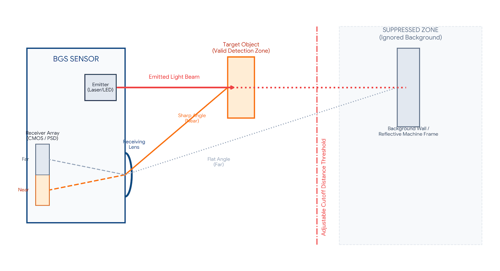
Unlike traditional diffuse reflective switches that evaluate the volume or amplitude of bounced light, a BGS sensor operates on the geometric principle of optical triangulation. Inside the unified sensor housing, the components are precisely structured:
-
The Emitter: A high-power visible red LED, an infrared (IR) light source, or a focused laser projects a clean optical beam through a transmitting lens directly onto the target path.
-
The Target Reflection: The surface of the passing target scatters and bounces the light. A portion of this scattered light returns through the receiving lens of the sensor.
-
The Receiver Array: Instead of hitting a single standard photodiode, the returning light strikes a specialized multi-element receiver, typically a Dual-Photodiode (Near/Far elements) or a multi-pixel CMOS linear array.
Because the emitter and receiver are physically separated by a fixed baseline distance inside the sensor body, the exact angle at which the returning light enters the receiving lens changes based on the distance of the target object. If the object is near, the reflected light enters at a sharp angle and strikes the “Near” segment of the receiver. If the object is further away, the angle flattens, causing the focused light spot to shift to the “Far” segment of the element array. By measuring the spatial position of the light spot on the receiver rather than its brightness, the sensor determines the exact position of the object.
Eliminating Color Dependency (Black-White Shift)
Because the internal microcontroller or electronic circuit evaluates the physical position of the light spot rather than the raw amount of returned light, the sensor becomes virtually color-blind. Whether a target is high-gloss white or ultra-matte black, the light spot hits the exact same physical coordinates on the receiver array if they pass at the same distance. This allows advanced industrial BGS modules to reduce the black-white distance deviation to a negligible 2% to 5%, maintaining sub-millimeter repeatability across demanding manufacturing runs.
Sensing Modes Compared: Background Suppression vs. Diffuse, Foreground, and Through-Beam
Selecting the optimal optical sensing mode requires matching the geometric layout of your machine with the optical properties of your target. Here is how BGS stacks up against alternative modalities:
| Sensing Mode | Background Management | Primary Advantages | Key Limitations |
| Background Suppression (BGS) | Completely suppresses and ignores everything beyond a set distance cutoff line. | Immune to target color/reflectivity shifts; ignores bright backgrounds nearby. | Shorter maximum range compared to through-beam; higher component precision. |
| Standard Diffuse | Cannot differentiate backgrounds; highly reflective backgrounds cause locked loops. | Low cost; simple single-unit installation; works well for open background zones. | Extremely vulnerable to target color changes (high Black-White Shift) and background glare. |
| Foreground Suppression (FGS) | Uses the permanent background (e.g., conveyor) as a reflector; triggers when blocked. | Excellent for highly irregular, glossy, or severely tilted specular parts. | Requires a continuous, physically stable background surface to aim at. |
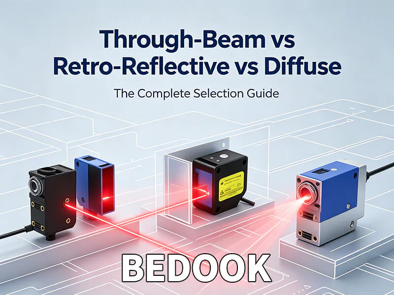
| Through-Beam | Not applicable; separate units face each other directly across the line. | Longest operating range; highest optical margin; easily cuts through thick dust/oil. | Requires mounting and wiring cables to both sides of the machine line. |
The Selection Decision Flow
Engineers should deploy a BGS Sensor when the target’s color, gloss level, or orientation changes continuously, but the background behind the line (such as a steel structural beam, aluminum guide rails, or passing personnel) remains fixed. Alternatively, choose Foreground Suppression (FGS) if you are trying to detect highly irregular, mirror-polished shiny objects that might deflect an incoming light beam completely away from the receiver lens. By focusing the FGS sensor directly on the stable conveyor bed instead of the part, any breakdown in the background baseline signal registers as a valid target detection.
Bedook BGS Product Portfolio & Performance Specifications
To meet diverse mechanical footprints and geometric constraints across international automation networks, Bedook provides a specialized suite of factory-direct background suppression solutions. These models are engineered with tailored optics to provide reliable performance within specific industrial envelopes:
| Product Series | Form Factor / Housing Style | Exact Detection Range | Target Industrial Application |
| FM18 Series |
Cylindrical M18 Threaded (Nickel-Plated Brass or Polymer) |
10 mm to 100 mm | Standard machinery retrofits; replaces standard proximity switches in traditional M18 mounting brackets where color variance causes false trips. |
| FQ21 Series |
Miniature Rectangular (Space-Saving Design) |
15 mm to 85 mm | Compact electronic assembly cells, semiconductor pick-and-place systems, and tight robotic end-of-arm tooling where space is heavily restricted. |
| FQ31 Series |
Standard Industrial Rectangular (Highly Versatile Workhorse) |
2 mm to 50 mm
10 mm to 100 mm
10 mm to 200 mm
10 mm to 250 mm |
High-speed packaging, clear-object presence detection, bottling tracks, and pharmaceutical lines. Offers multiple sub-ranges to optimize triangulation accuracy for specific conveyor widths. |
| FQ50 Series |
Long-Range Heavy-Duty Rectangular (Reinforced Housing) |
25 mm to 1000 mm | Large-scale material handling, logistics express hubs, automotive chassis assembly lines, and palletizing systems requiring up to 1 meter of clearance. |
Engineering Insight: Sourcing within the FQ31 series allows engineers to isolate ultra-close targets using the 2-50 mm micro-range, completely cutting off background noise just a couple of inches away, while the robust FQ50 series scales triangulation capability up to a full 1-meter threshold for large material handling applications.
Selection, Mounting, Wiring, and Installation Best Practices
Achieving a zero-maintenance, high-uptime installation requires strict adherence to geometric alignment rules and global electrical standards.
Crucial Lens Orientation Rules
When deploying rectangular BGS sensors (such as the Bedook FQ21, FQ31, or FQ50 series), the orientation of the internal optics relative to the target’s path of travel is critical to prevent double-triggering or timing jitter. The emitter and receiver lenses inside the housing are arranged in a straight linear path.
-
Correct Alignment: Always mount the sensor so that the linear axis connecting the emitter lens and receiver lens runs parallel to the direction of target movement. This ensures that as an object breaks the beam, the reflection angle transitions smoothly across the receiver array. If the sensor is rotated 90 degrees (lenses perpendicular to travel), any color boundaries or height variations on the moving part will cause a sudden, erratic shift of the light spot on the receiver, leading to false chattering outputs.
Universal Electrical Wiring Integration
To simplify global inventory management and reduce the number of individual stock-keeping units (SKUs) in a plant, Bedook BGS sensors utilize a 4-wire universal DC electrical configuration supporting concurrent outputs. This allows a single model number to handle multiple field requirements:
-
[Brown Wire] ——> Connect to +10-30V DC Power Supply
-
[Blue Wire] ——> Connect to 0V GND Baseline
-
[Black Wire] ——> Normally Open (NO) Output Signal (Active on Target Present)
-
[White Wire] ——> Normally Closed (NC) Output Signal (Active on Target Absent)
This design allows control engineers to select either NO or NC logic simply by landing the corresponding wire onto the PLC input card. Upgrading from standard potted PVC cabling to integrated M12 Threaded Quick-Disconnect Connectors is highly recommended for international facilities, enabling maintenance technicians to replace worn or cut cables in seconds without opening local junction boxes or running new conduit.
Troubleshooting, Calibration, and Real-World Tips
When a background suppression sensor exhibits erratic behavior on the plant floor, technicians can use the following systematic diagnostic routine to isolate and resolve the issue:
| Field Observation | Probable Root Cause | Recommended Corrective Action |
| Sensor ignores foreground target; yellow LED stays completely off. | Target is positioned inside the sensor’s optical dead zone (e.g., <2 mm for FQ31 or <25 mm for FQ50). | Adjust the mechanical mounting bracket to move the sensor further away from the active target travel path. |
| Sensor stays permanently locked ON even when no target is present. | The background structure is positioned inside the active cutoff threshold, or the lens face is heavily contaminated. | Clean the optical lens array with a lint-free microfiber cloth. Rotate the multi-turn sensitivity potentiometer counter-clockwise to pull the cutoff line closer. |
| Output chatters or double-triggers at the edge of multi-colored parts. | Sensor housing is rotated incorrectly, causing lenses to sit perpendicular to part movement. | Loosen the bracket hardware and rotate the sensor 90 degrees so the emitter/receiver optics align parallel with the conveyor flow. |
| Sensor works reliably on light targets but completely misses dark matte targets. | Extreme target absorption causing low signal margin, or threshold set too tight to the background line. | Perform a fresh dual-point calibration routine. If dust is high, clean the lens face or swap to an infrared (IR) light source model. |
Advanced Calibration: The Dual-Point Teach Protocol
For high-precision sorting lines or clear-object profiling, manual potentiometer tuning can be fine-tuned via digital teach-in mechanisms. The optimal method is the Dual-Point Teach-In:
-
Place the most challenging target (e.g., the matte black part or clear film) into the active tracking position and press the calibration button once. This registers the target position (Point A).
-
Remove the target completely, allowing the sensor to look directly at the background structure (e.g., the steel conveyor guide), and press the calibration button a second time. This registers the background position (Point B).
-
The internal microprocessor automatically calculates the perfect mathematical midpoint, setting a rock-solid electronic cutoff boundary that ignores background reflections while capturing low-reflectivity foreground parts.
Frequently Asked Questions (FAQ)
How exactly does a background suppression photoelectric sensor differ from a standard diffuse sensor?
A standard diffuse sensor measures the total intensity (brightness) of the returning light; if a background is highly reflective or shiny, it reflects more light than a dark target, causing a false trigger. A background suppression (BGS) sensor measures the physical angle of the returning light using optical triangulation, completely ignoring any reflections coming from objects located beyond the adjusted cutoff distance line, regardless of their color or brightness.
Can background suppression sensors reliably track targets at ultra-long ranges, like 6 to 10 feet?
Standard industrial BGS sensors are optimized for precise short-to-medium range tracking. Because triangulation requires measuring tiny geometric shifts of a light spot on an internal receiver element, the mechanical and optical resolution drops off over long distances. Bedook’s high-capacity FQ50 Series stretches BGS capability to an impressive maximum of 1000 mm (1 meter). For tracking across ranges of 6 feet or more, a Through-Beam or Polarized Retro-Reflective architecture remains the global industry standard.
How do I select the right background suppression model for my conveyor width and space constraints?
First, evaluate your physical space: if space is extremely tight, specify the miniature FQ21 Series (15-85 mm); if you need to mount into a standard pre-drilled bracket, the cylindrical FM18 Series (10-100 mm) is ideal. Second, match the conveyor envelope: for standard tracks, the FQ31 Series offers tailored sub-ranges (2-50mm, 10-100mm, 10-200mm, 10-250mm) to maximize triangulation resolution exactly where your product travels, while large logistics tracks require the FQ50 Series (25-1000 mm).
Optimize Global Procurement with Factory-Direct Bedook BGS Sensors
Sourcing high-performance optical automation components shouldn’t require paying massive markups to multi-tier distribution networks. Bedook has manufactured premium, globally compliant proximity switches and photoelectric sensors for nearly 30 years. Our advanced Background Suppression Series offers drop-in component interchangeability with premium legacy international brands, combined with factory-direct wholesale pricing, robust product availability, and direct engineering support.
Ready to Upgrade Your Sourcing Strategy? Prepare these 4 simple data points before contacting our international sales desk to ensure a seamless drop-in match:
-
Target Working Distance Envelope (e.g., 150 mm tracking depth)
-
Target Material & Color Profile (e.g., matte black rubber, clear blister packs, or glossy cartons)
-
Control System Electrical Logic & Connection (PNP vs. NPN, M12 Connector vs. Potted Cable)
-
Current Legacy Part Number (Omron, Sick, Keyence, or Banner for exact cross-referencing)
[Submit Your Application Specifications for a Free Technical Cross-Reference]
Explore Bedook: Your Trusted Sensor Manufacturer
At Bedook, we specialize in designing, developing, and manufacturing a comprehensive range of proximity sensors and switches. Our extensive product lineup includes:
- Inductive Proximity Sensors
- Capacitive Proximity Sensors
- Photoelectric Sensors
- Ultrasonic Sensors
- Solid State Relays
- Various Accessories
With over 10,000 detailed product variations and a robust R&D team, we take pride in our ability to meet your unique requirements with tailored solutions and reliable performance.
Whether you’re seeking off-the-shelf products or customized designs, Bedook offers the expertise and production capacity to ensure your satisfaction.
Get in Touch Today!
We value your interest in our products and warmly encourage you to send us an inquiry. Let us help you find the perfect sensor solution for your application.
Thank you for considering Bedook—your trusted partner in innovation and quality manufacturing. We look forward to collaborating with you!
 Through-Beam vs Retro-Reflective vs Diffuse Photoelectric Sensors: The Complete Selection Guide
 The Ultimate Guide to Selecting a Photoelectric Fork Sensor for High-Speed Counting